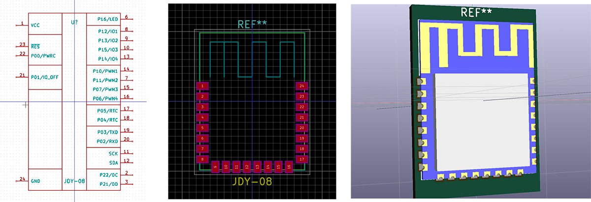
JDY-08 Bluetooth transparent transmission module
Feature
- Tested on 3V3
- Module enter into data transmission mode when it paired.
- Pull P00 to low to wake up the module from sleep mode, then module can accept data tranmission.
- serial data send need “/r/n”
- Power supply must use 3.3 or 3V for final products
- master module can only allow one slave module connect
- in room distance is 15-30 meters, max to 60 meters.
- Tranmission data speed is 1KB/s
- Do not support 2.0 or 3.0 bluetooth version.
Operating mode state current
- Slave Transparent Mode Connected / Not Connected / Standby 0.8mA / 300uA / 1uA
- Slave Broadcast mode (IBeacon, sensor) Connection / Not connected / Standby 0.5mA / 300uA / 1uA
- Host Transmitted Mode Connect / Unconnected / Standby 20mA / 9mA / 1uA
- Host observer mode (Sensor) connected / not connected / standby 25mA
Dimension, Pin definition

Pin definition
- VCC Power Supply Power supply 3V or 3.3V
- P22
- P21
- P20
- P17
- P16 connection status pin Bluetooth connection is low, usually high (master-slave effective)
- P11 PWM2 The PWM2 output pin can be controlled by the APP
- P12 IO1 Output The IO1 pin can be controlled by the APP level
- P13 IO2 Output The IO2 pin can be controlled by the APP pin
- P15 IO3 Output The IO3 pin can be controlled by the APP pin
- SCK
- SDA
- P14 IO4 Output The IO4 pin can be controlled by the APP pin
- P10 PWM1 The PWM1 output pin can be controlled by the APP
- P07 PWM3 The PWM3 output pin can be controlled by the APP
- P06 PWM4 The PWM4 output pin can be controlled by the APP
- P05 RTC Alarm IO IO output low when the RTC timing time expires
- P04 RTC Alarm IO IO output low when the RTC timing time expires
- P03 TXD serial output, the level is TTL level
- P02 RXD serial port, the level is TTL level
- P01 IO disconnected Bluetooth connection status is down to delay the connection, usually high
- P00 PWRC module sleep wake-up pin, the module internal pull-up resistor, low-level wake-up, usually high
- RST Resets the hardware reset pin
- GND Power ground
Boards:
- Resources a simple breakout board design for development. By Danny Staple (Orionrobots)
Resources for development in KiCAD…
AT Commands
- AT + RST reset M / S -
- AT + BOUD serial port baud rate setting M / S - 115200
- AT + HOSTEN Master / Slave Setup M / S - Slave
- AT + HOST Read Host Status M -
- AT + DISC Disconnect M -
- AT + ADVEN Open Broadcast S - On
- AT + ADVIN Broadcast interval S - 100ms
- AT + NEIN Connection Interval S - 10ms
- AT + POWR Transmit power S - 0db
- AT + NAME broadcast name S - EB - 08
- AT + MAC Read MAC Address M / S -
- AT + STRUUID Set iBeacon UUID (string type UUID) S iBeacon UUID
- AT + HEXUUID setting iBeacon UUID (hexadecimal type UUID) S iBeacon micro letter UUID
- AT + MAJOR Sets iBeacon Major (string type Major)
- AT + MINOR Set iBeacon Minor (string type Minor) S iBeacon 7
- AT + VER Read version number M / S - JDY-08-2.1
- AT + VID Manufacturer’s identification number (not for factory identification) S iBeacon Sensor 8899
- AT + TEMP Temperature Value Sets the Sipacon sensor
- AT + HUMID Temperature setting S iBeacon sensor 0
- AT + ISCEN Set whether to open the password connection S - Off
- AT + PASS connection password S - 123456
- AT + SVRUUID Change service UUID M / S - FFE0
- AT + CHRUUID Change feature UUID M / S - FFE1
- AT + SCAN Host Scan Slave M Host transparently transmitted
- AT + RSLV Reads the MAC-to-MAC transparent transmission from the master
- AT + CONNET CONNECTIONS SCAN TO MAC MOST TRANSMISSION FROM SLAVE
- AT + BAND Bind slave MAC M -
- AT + GETDCD Number of slaves scanned by the master M -
- AT + GETSTAT Find the working status of the module M / S -
- AT + PWMFRE Set the PWM frequency M / S - 500HZ
- AT + PWMOPEN Turns PWM M / S - off
- AT + PWM1PUS Sets the pulse width of PWM1 M / S - 50%
- AT + PWM2PUS Sets the PWM2 pulse width M / S - 50%
- AT + PWM3PUS Sets the pulse width of PWM3 M / S - 50%
- AT + PWM4PUS Sets the pulse width of PWM4 M / S - 50%
- AT + RTCDATE Setting the RTC time M / S -
- AT + RTCOPEN Turn on the RTC function M / S - Off
- AT + WXSVR Micro-H5 communicates with the server settings S-micro-H5
AT instructions
| Commands | AT | return |
|---|---|---|
| Soft reset | AT + RST | Returns: OK |
| Setting the baud rate Note: The module default baud rate is 115200 | Instruction: AT + BOUD0 means the baud rate is 115200, 1 means the baud rate is 57600, 2 means the baud rate is 38400, 3 means the baud rate is 19200, 4 means the baud rate is 9600 | Returns: OK |
| Set the module operating mode | AT + HOSTEN0 means to set the slave transparent transmission (APP) mode. 1 means to set the host transparent mode, 2 means to set the host (indoor positioning, sensor) observer mode, 3 means to set the host (indoor positioning, sensor) observer mode, 4 means to set the slave (WeChat transmission) mode | Returns: OK |
| Disconnect | AT + DISC Disconnect | Returns: OK |
| Open the radio | Command: AT + ADVEN0 Stop broadcasting, AT + ADVEN1 means to turn on the broadcast, do not turn on the radio after power on | Returns: OK |
| Broadcast interval | Instruction: AT + ADVIN0 means to set the broadcast interval to: 100ms, 1 means to set the broadcast interval to: 500ms, Instruction: AT + ADVIN2 means to set the broadcast interval to: 750ms, Instruction: AT + ADVIN3 means to set the broadcast interval to: 1000ms, Instruction: AT + ADVIN4 means to set the broadcast interval: 2000ms, Instruction: AT + ADVIN5 means to set the broadcast interval to: 4000ms, Instruction: AT + ADVIN6 means to set the broadcast interval to: 8000ms | Returns: OK |
| Connection Interval | Instruction: AT + NEIN0 connection is 10ms, Command: AT + NEIN1 connection is 100ms, Command: AT + NEIN2 connection is 500ms | Returns: OK |
| Transmission power | Instruction: AT + POWR0 that set the transmit power to 4db CC2541 module this is 0db, Command: AT + POWR1 means to set the transmit power to 0db, Command: AT + POWR2 that set the transmit power -6db, Command: AT + POWR3 means to set the transmit power to -23db | Returns: OK |
| Transmission power | Instruction: The AT + POWR instruction is followed by a read without parameters | Returns: POWR0db indicates that the module transmit power is: 0db |
| Set the broadcast name | Instruction: AT + NAMEEB-08 means to set the broadcast name: EB-08 | Returns: OK |
| Set the broadcast name | Instruction: The AT + NAME instruction is followed by a read without parameters | Returns: JDY-08 Indicates that the module broadcast is named JDY-08 |
| Reads the MAC address | Instruction: AT + MAC | Returns: MAC: 001830EA0662 Indicates that the MAC address is: 001830EA0662 |
| Set the iBeacon UUID | The string type UUID is set, UUID is: FDA50693A4E24FB1AFCFC6EB07647825 <ul><li> Command: AT + STRUUIDFDA50693A4E24FB1AFCFC6EB07647825 </li></ul> | Returns: OK |
| Set as UUID in hexadecimal, UUID is: FDA50693A4E24FB1AFCFC6EB07647825 | Directive: 41542b48455855554944FDA50693A4E24FB1AFCFC6EB07647825 | Returns: OK |
| Set as UUID in hexadecimal | Instruction: The AT + STRUUID instruction is followed by a read without parameters | Returns: UUID: FDA50693A4E24FB1AFCFC6EB07647825 |
| Reads the UUID in hexadecimal | Command: AT + HEXUUID | Return: 555549443AFDA50693A4E24FB1AFCFC6EB07647825 |
| Set iBeacon Major | Command: AT + MAJOR000A Indicates that Major is set to 10 | Returns: OK |
| Set iBeacon Major | Instruction: The AT + MAJOR instruction is followed by a read without parameters | Returns: 4D414A4F523A000A Returns the data in hexadecimal format Major: 0x000a |
| Set iBeacon Minor | Command: AT + MINOR0007 means to set Minor to 7 | Returns: OK |
| Set iBeacon Minor | Command: The AT + MINOR instruction is followed by a read without parameters | Returns: 4D494E4F523A0007 Returns the data in hexadecimal format Minor: 0x0007 |
| Read the module version number | Command: AT + VER instruction is not behind the parameters that read | Back to: EB-08-V2.1 |
| Set the factory identification code | Command: AT + VID1122 means to set the factory identification code to 1122 | Returns: OK |
| Set the factory identification code | Command: AT + VID Read the factory identification code | Returns: VID: 1122 |
| Set the sensor temperature value | Command: AT + TEMP32 means the setting temperature is 32 degrees | Returns: OK |
| Set the sensor humidity value | Command: AT + HUMID11 means that the relative humidity is set to 11% | Returns: OK |
| Set the sensor charge value | Command: AT + BATT90 means that the sensor power is 90% | Returns: OK |
| Set whether to open the password connection | Command: AT + ISCEN0 means close the password connection <ul><li> Command: AT + ISCEN1 means open the password connection but not binding </li><li> Command: AT + ISCEN2 means open the password connection and bind </li></ul> | Returns: OK <ul><li> Note: The factory default is to disable the password connection </li></ul> |
| Set the connection password | Command: AT + PASS123456 means to set the connection password: 123456 password length can only be 6 | Returns: OK |
| Set the connection password | Command: AT + PASS means to read the connection password | Returns: PSS: 123456 <ul><li> Note: The factory default password: 123456 </li></ul> |
| Change the service UUID | Instruction: AT + SVRUUFFFF0 means set service UUID is: 0xFFF0 | Returns: OK |
| Change the service UUID | Command: AT + SVRUUID Indicates the read service UUID | Returns: SRUUID: FFF0 |
| Change the pass-through feature UUID | Instruction: AT + CHRUUIDFFF1 means setting the characteristic UUID to be: 0XFFF0 | Returns: OK |
| Change the pass-through feature UUID | Command: AT + CHRUUID Reads the feature UUID | Returns: SRUUID: FFF1 |
| Host scan | Command: AT + SCAN1 Indicates that the master starts scanning the slave <ul><li> Command: AT + SCAN0 indicates that the master stops scanning the slave </li></ul> | Returns: OK |
| The host reads the number of slaves scanned | Command: AT + GETDCD | Returns: DEV: 1 indicates that the host has scanned a device and can scan up to 8 devices |
| The master reads the scanned slave MAC address | Instruction: AT + RSLV0 means the host reads the MAC address of list 0, and can read up to 8 lists of addresses | Returns: MAC: 001830EA0662 |
| The address of the list to which the host connection is scanned | Command: AT + CONNET0 Indicates the MAC address of host connection list 0 | Returns: OK |
| The MAC address that the host binds to | Command: AT + BAND0 Indicates the MAC address of Host Binding List 0 | Returns: OK |
| The MAC address that the host binds to | Command: AT + BAND001830EA0662 Indicates that the host binds the specified MAC address: 001830EA0662 | Returns: OK |
| The MAC address that the host binds to | Command: AT + BAND Reads the bound MAC address | Returns: MAC: 001830EA0662 |
| Read the working status of the module | Command: AT + GETSTAT | The following is the return status of each operating mode <ul><li> 1: Slave transmission mode </li><li> Returns: STS: 0111 </li><li> The stunning part corresponds to the left function </li><li> Operating mode - STS: 0111 0 Indicates transparent mode for the slave </li><li> Connection status - STS: 0111 1 means connected, 0 means not connected </li><li> Broadcasting - STS: 0111 1 means that the broadcast is enabled and 0 means it is off </li><li> Open password connection - STS: 0111 1 means to play password connection, 0 means not open in this case, </li></ul><ul><li> 2: Host transparent mode </li><li> Returns: STS: 10 </li><li> 1: Indicates the host transparent transmission mode </li><li> 0: Connected, 1: Connected </li></ul><ul><li> 3: Slave iBeacon mode </li><li> Returns: STS: 301 </li><li> 3: Indicates the iBacon mode </li><li> 0: Not connected, 1: Connected </li><li> 1: Indicates that the broadcast is on, and 0 means that the broadcast is not turned on </li><li> 4: Host observer mode </li><li> Returns: STS: 2 </li><li> 2: Indicates the host observer mode </li></ul> |
| PWM frequency setting | Command: AT + PWMFRE260 means to set the PWM frequency to 260HZ | Returns: OK |
| PWM frequency setting | Command: AT + PWMFRE Read the PWM frequency | |
| Turn on the PWM function | Command: AT + PWMOPEN1 Indicates that the PWM is turned on <ul><li> Command: AT + PWMOPEN0 means to turn off PWM </li></ul> | Returns: OK |
| Turn on the PWM function | Instruction: AT + PWMOPEN Read PWM operation state | Returns: PWMOPEN: 1 for development, 0 for off |
| Set the PWM1 pulse width | Instruction: AT + PWM1PUS50 means to set the pulse width of PWM1 to 50% | Returns: OK |
| Set the PWM2 pulse width | Instruction: AT + PWM2PUS10 means to set the pulse width of PWM2 to 10% | Returns: OK |
| Set the PWM3 pulse width | Instruction: AT + PWM3PUS90 means to set the pulse width of PWM3 to 90% | Returns: OK |
| Set the PWM4 pulse width | Instruction: AT + PWM4PUS80 means setting pulse width of PWM4 to 80% | Returns: OK |
| Set the RTC time | Instruction: AT + RTCDATE2014-12-05,12: 07: 08, Indicates that the RTC time is set to December 5, 2014, 12: 7: 8 | Returns: OK |
| Set the RTC time | Command: AT + RTCDATE Read RTC time | Return: AT + RTCDATE14-12-05, 12: 07: 09, Indicates that the read RTC time is December 5, 2014, 12:7:9 |
| RTC function switch | Command: AT + RTCOPEN0 means to turn off the RTC <ul><li> Command: AT + RTCOPEN1 Indicates that the RTC is on </li><li> Command: AT + RTCOPEN2 Indicates that the RTC is turned on and turned on </li></ul> | Returns: OK |
| Micro-H5 or server selection | Command: AT + WXSVR0 Indicates communication with micro-H5 <ul><li> Command: AT + WXSVR1 indicates communication with the factory server via micro-communication </li></ul> | Returns: OK |
| Micro-H5 or server selection | Command: AT + WXSVR Read status | Returns: 0 for WXSVR: 0 for return status H5 for factory manufacturer server |
Devices End Instructions
- Phone side command
| Name | Instructions |
|---|---|
| UUID list | * Service UUID: 0XFFE0 (service UUID default 0xffe0 user can change) <ul><li> FEATURES UUID: 0XFFE1 (for transparent transmission of the default 0xffe1UUID user can change)</li><li> Feature UUID: 0XFFE2 (for module function configuration)</li></ul> |
- WeChat UUID list, not listed here
- APP instructions for use
| Name | Feature UUID | Description | Commands | Return |
|---|---|---|---|---|
| 1) APP transparent transmission | UUID: 0XFFE1 | FFE1 for the APP transparent transmission characteristics UUID <ul><li> (applied to the IOS or Android phone through the APP) </li></ul> | ||
| 2) IBeacon UUID settings and read | UUID: 0XFFE2 | Set the UUID instruction format: E1 + 11 + 16 hexadecimal UUID | Instruction: <ul><li> E111FDA50693A4E24FB1AFCFC6EB07647825 </li></ul> | |
| 2) IBeacon UUID settings and read | UUID: 0XFFE2 | Read the UUID instruction format: E1 +12 | Instruction: E112 | Back to: <ul><li> 12FDA50693A4E24FB1AFCFC6EB07647825 </li><li> 12 for the command header, FDA50693A4E24FB1AFCFC6EB07647820 for the UUID </li></ul> |
| 3) IBeacon Major settings and read | UUID: 0XFFE2 | Set Major Instruction Format: E2 +21 + 2 Hexadecimal | Instruction: E221000A Description Major is hexadecimal 000A | |
| 3) IBeacon Major settings and read | UUID: 0XFFE2 | Read the Major | instruction: E222 | Returns: <ul><li> 22000A Description 22 for the command header, 000A for the hexadecimal Major </li></ul> |
| 4) IBeacon Mimor set and read | UUID: 0XFFE2 | Set the broadcast interval | instruction format: E3 +41 + 2 hexadecimal Minor <ul><li> Command: E3320007 means to set Mmior to hex 0X0007 </li><li> Command: E332 means reading the Minor hexadecimal value </li></ul> | Returns: 320007 Description 32 is the command header, 0007 is the hexadecimal Minor |
| 4) Broadcast interval setting and reading | UUID: 0XFFE2 | Set the broadcast interval | instruction format: E4 +41 + 1 hexadecimal data <ul><li> Command: E44100 means to set the broadcast interval to 100ms </li><li>Command: E442 Indicates read broadcast interval </li></ul> | Returns: 4200 Description 42 is the command header, 00 means the broadcast interval is: 100ms <ul><li> The APP sends the command broadcast interval </li><li> E44200 100ms </li><li> E44201 500ms </li><li> E44202 750ms </li><li> E44203 1000ms </li><li> E44204 2000ms </li><li> E44205 4000ms </li><li> E44206 8000ms </li></ul> |
| 5) Connect password settings and read | UUID: 0XFFE2 | Set the connection password | Instruction format: E5 + 51 + 6-bit current password + 6-bit new password <ul><li> Instructions: E551313233343536313132323333 </li><li> said after the set of passwords: 11223344 </li><li> The new password can be set only when the current password is the same as the module password, and the password before the password is updated will be invalid </li></ul> | |
| 6) Broadcast name setting and reading | UUID: 0XFFE2 | Set broadcast command format: E6 + 61 + broadcast name (broadcast name length of not more than 12 bytes) | Instruction: E6614A44592D3038 means to set the broadcast name: EB-08 <ul><li> Command: E662 Indicates read broadcast name </li></ul> | Return: 624A44592D3038 Description 62 for the command header, 4A44592D3038 said broadcast name: EB-08 |
| 7) APP control IO port | UUID: 0XFFE2 | IO1 | <ul><li> E7F100 IO1 output low level </li><li> E7F101 IO1 output high level </li></ul> | Command: E7F101 means to set IO1 high level |
| 7) APP control IO port | UUID: 0XFFE2 | IO2 | <ul><li> E7F200 IO2 output low </li><li> E7F201 IO2 output high </li></ul> | Command: E7F101 means to set IO1 high level |
| 7) APP control IO port | UUID: 0XFFE2 | IO3 | <ul><li> E7F300 IO3 output low level </li><li> E7F301 IO3 output high level </li></ul> | Command: E7F101 means to set IO1 high level |
| 7) APP control IO port | UUID: 0XFFE2 | IO4 | <ul><li> E7F400 IO4 output low level </li><li> E7F401 IO4 output high level </li></ul> | Command: E7F101 means to set IO1 high level |
| 8) APP control PWM switch | UUID: 0XFFE2 | ON/OFF | * PWM OFF E8A100 None <ul><li> PWM on E8A101 None </li><li> PWM ON/OFF on boot E8A102 None </li></ul> | |
| 8) APP control PWM switch | UUID: 0XFFE2 | PWM frequency setting (frequency range 50-4KHZ) | PWM frequency is set to 1000HZ E8A203E8 None | |
| 8) APP control PWM switch | UUID: 0XFFE2 | PWM Tempo Setting (Range 0-99%) | <ul><li> PWM1 Temporary Ratio set to 10% E8A30A None </li><li> PWM2 Temporal Ratio set to 50% E8A432 None </li><li> PWM3 Temporal Ratio set to 90% E8A55A None </li><li> PWM4 Temporal Ratio set to 30% E8A61E None </li></ul> | |
| 8) APP control PWM switch | UUID: 0XFFE2 | Read PWM state <ul><li> Read PWM switch state E8A8 </li></ul> | A831 indicates PWM on state <ul><li> A830 indicates the PWM off state </li></ul> | |
| 8) APP control PWM switch | UUID: 0XFFE2 | Read PWM frequency | Read PWM frequency E8A9 A903E8 indicates that the frequency is 1000HZ <ul><li> Read PWM1 Temporal Ratio E8AA AA0A Indicates Temporary Ratio is 10% </li><li> Read PWM2 Temporal Ratio E8AB AB32 Indicates Temporary Ratio is 50% </li><li> Read PWM3 Temporal Ratio E8AC AC5A Indicates a temporary ratio of 90% </li><li> Read PWM4 Temporary Ratio E8AD AD1E Indicates Temporary Ratio is 30% </li></ul> | |
| 9) APP control Other | UUID: 0XFFE2 | Instruction: E90101 represents the reset module, | Command: E90102 means disconnect the Bluetooth connection, (this feature applies only to the slave mode) | |
| 10) APP control of transmit power | UUID: 0XFFE2 | control of transmit power | * 4db EAC100 indicates that the transmit power is set to 4db, CC2541 module is: 0db <ul><li> 0db EAC101 means to set the transmit power to 0db </li><li> -6db EAC102 means to set the transmit power to -6db </li><li> -23db EAC103 means to set the transmit power to -23db </li></ul> | |
| 10) APP control of transmit power | UUID: 0XFFE2 | Read transmit power | EAC2 | returns C201 that transmit power is: 0db |
| 11) APP control RTC | UUID: 0XFFE2) | on off, on on boot | * RTC Off EBB100 None <ul><li> RTC On EBB101 None </li><li> RTC On and Power On EBB102 None </li></ul> | - |
| 11) APP control RTC | UUID: 0XFFE2) | Set the RTC time, For: May 7, 15 years, 9 hours 9 seconds seconds | EBB20F0507090900 | None |
| 11) APP control RTC | UUID: 0XFFE2) | Read the RTC time | EBB3 | B30F0507090900, Said that at 9:10 on May 7, 15 seconds |
Working Mode Wiring
Working Mode
Working in relay control mode
use app “IO_ctrl”, when button on bluetooh board pressed, app will receive relevant UUID data, when switch in app is pressed, UUID will send to EB08
iBeacon mode
- Step 1: Configure the module as an iBeacon mode command
- Send via serial port: AT + HOSTEN3 Returns: OK
- Step 2: Let the module restart
- Send via serial port: AT + RST means reset
- Step 3: Change the UBID of iBeacon to (FDA50693A4E24FB1AFCFC6EB07647825)
- Send via serial port: AT + STRUUIDFDA50693A4E24FB1AFCFC6EB07647825 Back: OK
- Step 4: Change the Major value of iBeacon to (10)
- Send via serial port: AT + MAJOR000A returns OK
- Step 5: Change the minor value of iBeacon to (7)
- Send via serial port: AT + MINOR0007 Returns OK
- Also set manufactuer ID is necessary, because the factory set of UUID is the same:
- The factory ID is 65330 (decimal value) and the hexadecimal value is 1985
- Send via serial port: AT + VID1985 Returns: OK
PWM Cotrol
- The first step to set the PWM frequency is 250Hz (frequency range is 50 - 4KHZ)
- AT command: AT + PWMFRE250 returns OK
- The second step turns on the PWM
- AT command: AT + PWMOPEN1 return OK (1 is not open to open the PWM, 2 is turned on)
- The third step to open the set PWM pulse width (4-way PWM output, so you can set the 4-way PWM pulse width)
- AT command: AT + PWM1PUS90 return OK to set PWM1 pulse width is 90%
- AT command: AT + PWM2PUS10 return OK to set PWM2 pulse width is 10%
- The following are PWM3 and PWM4 settings, not one by one here about
- The fourth step user can read the working status of PWM
- AT command: AT + PWMPUS return to the state, see the manual
- Step 5 Turn off the PWM function
- AT command: AT + PWMOPEN0 This module will turn off the PWM function, and if the PWRC pin is high
- Level, the module will enter the low-power mode,
iBeacon Sensor
- Step 1: Configure the module to iBeacon mode
- Note that the sensor function is only applied in the iBeacon mode, so you need to configure the iBeacon mode
- Send via serial port: AT + HOSTEN3 Returns: OK
- Step 2: Let the module restart
- Send via serial port: AT + RST means reset
- Step 3: Set the temperature to 33 degrees
- Send via serial port: AT + TEMP33 Returns: OK
- Step 4: Set the humidity value to 11%
- Send via serial port: AT + HUMID11 returns OK
- Step 5: Set the power of the sensor to 90%
- Send via serial port: AT + BATT90 returns OK
- Since the sensor function is based on the iBeacon application, if your sensor is numerous, the above two sensor commands
- Can not meet your product applications, you can use iBeacon related instructions to transmit your sensor data
- AT + STRUUID + 32-bit string length, please note that this 32-bit data format: Hexadecimal string
- AT + MAJOR + 4-bit string length, the string format: hexadecimal string
- AT + MINOR + 4-bit string length, the string format: hexadecimal string
Power Consumption Setup
- The default broadcast interval is the smallest, due to different user’s product requirements, the power consumption of products have great requirements, so our module also considered this, the module can broadcast interval is set by AT command
- The default broadcast interval is: AT + ADVIN0 is 100 ms
- Users need to have certain requirements for power consumption can be set by AT + ADVIN broadcast interval
- The AT command broadcasts the time current
- AT + ADVIN0 100ms 0.6mA
- AT + ADVIN1 500ms 0.1mA
- AT + ADVIN2 750ms 0.05mA
- AT + ADVIN3 1000ms 0.02mA
- The above is set by the AT command, the user can also set the broadcast interval through the phone, not the longer the better the broadcast interval, the broadcast interval is too long will affect the connection time, is to be a long time to connect with the phone, the general set 100 or 500ms About the same, the sensor application can be set up a little longer, because no connection
- Connection interval settings
- Users can connect with the phone when the current can be set, you can AT command or phone to set the AT command can be set by: AT + NEIN to set
- The AT command broadcasts the time current
- AT + NEIN0 10ms 0.8mA
- AT + NEIN1 100ms 0.2mA
- AT + NEIN2 500ms 0.05mA
- The above is through the AT command to set the connection interval, the user can also set the connection interval through the phone, not the connection interval set the longer the better, but also depends on the user to determine the use of the scene, the longer the interval does not adapt to penetration, If the general requirements for the default interval can be, if only some control applications, or small data should be, then the connection interval can be set a little longer.
Master to Slave, two bluetooth mode
- Master-slave Bluetooth module communication refers to two Bluetooth modules communicate with each other, one for the host, a slave, they communicate with each other, the first module for the slave module, the second module is the host module
- The first step will host and slave module power and the module serial port and USB serial or MCU serial port connection, pay attention to the need to cross the serial line, connect the AT command to start debugging
- The second step will be the first module from the machine to open the radio, the default is to open the broadcast from the machine, but also by sending AT + ADVEN1 to open the broadcast
- Step 3: Set the commands of the main module
- 1) Set the module to host transparent mode, return OK to complete the set send command: AT + HOSTEN1 return OK
- 2) Set the module to restart
- Send: AT + RST
- 3) Scan the surrounding BLE command
- Send: T + SCAN1 Returns OK
- 4) Read the number of BLE Bluetooth scanned (up to 8 slaves)
- AT + GETDCD returns DEV: 1 means scanning to a device
- 5) Read the slave MAC address of the scan list (0-7)
- Send: AT + RSLV0 Returns: MAC: e3435480
- 6) Connection scan list 0 device (0-7)
- Send: AT + CONNET0
- 7) Send the command to find out whether it is connected with the slave
- Send: AT + GETSTAT Returns: STS: 11 Indicates that the connection has been made
- 8) The hardware judges whether it has been connected with the slave
- Module 6 pin for the connection status pin, the connection is successful for the low, not connected to high
- 9) host and slave connection is successful, you can transparently transfer data
Master/slave pair/binding mode for data tranmissoin
- Sets the command for the master module
- 1) Set the module to host transparent mode, return OK to complete the setup
- Send command: AT + HOSTEN1 returns OK
- 2) Set the module to restart
- Send: AT + RST
- 3) The host binds the slave MAC address
- Send the command: AT + BAND884AEA478140 to return OK
- 4) The hardware judges whether it has been connected with the slave
- Module 6 pin for the connection status pin, the connection is successful for the low, not connected to high
- 5) After the host and the slave connection is successful, you can pass through the data, and binding only once, the next power does not need to
- Time binding, later used as long as the binding of the slave in the host communication range, the host will automatically connect with the slave, the connection, they can be transparent between the data.
- 6) Unbind the slave
- Send: AT + CLRBAND Returns OK
- As a result of the binding from the machine, the host will have been connected with the binding from the machine, even if the machine is closed, the host will search around to see if there is bound from the machine, if there is to connect with it, After the host will no longer be bound with the slave to connect,
- Note: When the above host binds the MAC address of the slave, you need to know the MAC address of the slave. The MAC address of the slave can be read by AT + MAC.
Sensor read function
- Connect the serial port (RXD, TXD) of the USB serial or MCU to the module, and connect the PWRC pin of the module to the power supply (VCC, GND) of the module when sending commands using the serial port. , The supply voltage is 3.3V or 3V
- According to the above connection line, began to talk about the AT command operation
- Step 1: Configure the module as a host observer
- Send via serial port: AT + HOSTEN2 Returns: OK
- Step 2: Let the module restart
- Send via serial port: AT + RST means reset
- Through the above settings, the module has been configured for the host observer mode, then start the host machine to receive the data from the sensor, the host serial port to receive the sensor data format is as follows
- (+) Byte (byte) VID + 1 (byte) TEMP + 1 (byte) DATA format: 2 (bytes) Head + 6 (bytes) MAC + 1 (byte) RSSI + + 1 (bytes) BATT
- The user can identify their own sensor data through the VID, and then distinguish each sensor by MAC address
- Note: the data received by the host MAJOR, MINOR, VID, TEMP, HUMID, BATT corresponds to the slave transmission
- The data sent by the AT command in the sensor mode
- AT + MAJOR000A
- AT + MINOR0007
- AT + VID6677
- AT + TEMP44
- AT + TEMP44
- AT + BATT90
Replace your module by UUID
- For example, before you use the transparent module UUID service for the 0XFFF0, features UUID 0XFFF1,
- You only need to send these two commands to change the service UUID and feature UUID of our module.
- Send via serial port:
- AT + SVRUUIDFFF0 Returns: OK
- AT + CHRUUIDFFF1 Returns: OK